

Simulation analysis of mechanical influence of water level fluctuation in water-eroded groove on tunnel lining
-
摘要: 岩溶隧道通常面临季节性溶槽水位波动带来的水害风险,文章结合工程案例,通过数值模拟,量化分析不同水位和不同位置溶槽蓄水对隧道衬砌受力影响,以揭示隧道水害风险的发生机制和演化特征,主要结论:(1)溶槽在季节性强降雨时发生水位波动,隧道外水压力变化频繁,导致隧道衬砌内力变化显著;水位升高时,结构受力恶化,安全性大幅削减,其中拱顶、边墙仍以小偏心受压模式承载,而隧底部位承载模式由小偏心受压逐步发展为大偏心受压;高水位时衬砌结构存在开裂、破损的风险;(2)边墙部位溶槽蓄水对隧道造成偏压水荷载,边墙安全系数最高下降1.1;地下水位上升,偏压水荷载逐渐演化为均布水荷载,结构受力影响差异性逐渐减小;(3)季节性强降雨来袭,加强泄水降压是解决水头上升、水压过大致使衬砌破坏的关键,并重点关注边墙、隧底衬砌结构安全。Abstract:
Karst tunnels are usually faced with the risk of water disaster caused by seasonal fluctuation of water level in water-eroded groove. Due to seasonal precipitation, water supply and other reasons, water storage structures such as karst caves and underground rivers are in the state of low water level in the dry season. When the rainy season comes, the groundwater level rises rapidly due to water supply of these water storage structures, and water accumulates behind the tunnel lining through water-eroded groove or karst fissure (karst pore). The water pressure of tunnel lining increases sharply, which seriously threatens the safety of lining structure. Through relevant investigation, the authors learn that a heavy rainfall caused a section of lining to break, and this section had to be repaired during the construction of Yunwushan tunnel on Yiwan railway. Besides, during the construction of Yinshan tunnel in Guizhou Province, a rare rainstorm occurred, and the vertical side wall of the tunnel was crushed by sudden karst water, with the destruction length of the side wall reaching 20 m. Another example is when the construction of Jijiapo tunnel passed through the karst area in Hubei Province, the water pressure behind the lining increased sharply during the heavy rainstorm, which resulted in serious fracturing of the second lining and the bottom plate as well as water gushing due to bottom drum rupture of the construction joint. Macro influences of karst groundwater on tunnel lining structure have been studied by a large number of scholars through numerical simulation and field test. However, most of them are qualitative analyses insufficient in the study on external water pressure of tunnel lining in karst areas, and do not highlight the distribution characteristics of external water pressure of lining under fluctuating water level of water-eroded groove. Therefore, these studies can hardly reflect the actual influence of karst groundwater on lining structure in terms of the calculation with load-structure method. Based on the engineering case of a highway tunnel in the karst area of Southwest China, this study quantitatively analyzes, through numerical simulation, the influence of different groundwater levels and different locations of water storage in water-eroded grooves on the stress of tunnel lining. The research process is shown as follows. According to the results of geological exploration and groundwater connectivity test under on-site rainfall conditions, the typical cross-section of the tunnel was firstly selected. Subsequently, the external water pressure of tunnel at different water levels was calculated through seepage software, which was followed by the calculation of the surrounding rock pressure according to the specifications. Finally, the internal force of the lining was calculated through the "load-structure" method. According to the careful analysis and scientific judgment, the occurrence mechanism and evolution characteristics of the tunnel water hazard risk were revealed. The main conclusions indicate as follows. (1) The water level fluctuates in water-eroded groove under seasonal heavy rainfall, and the pressure of water outside the tunnel changes frequently, which results in significant changes of internal force of tunnel lining. When the water level rises, the structural stress increases and the safety will greatly reduce. The arch and side walls are still loaded in the mode of small eccentric compression, while the mode of loading at the bottom of the tunnel gradually develops from small eccentric compression to large eccentric compression. There exists the risk of cracking and breakage of lining structure at high water level. (2) The water storage of water-eroded groove at the side wall of the tunnel results in bias water load on the tunnel, and the safety factor of the side wall decreases by up to 1.1. The safety factor of tunnel lining at the same water level is less than that of the corresponding position on the other side, with the difference of safety factor between 0.1 and 0.3. With the gradual increase of groundwater level, the difference shows a decreasing trend, i.e. from bias water load to even water load, and the influence on structural force difference gradually reduces. (3) Under the condition of high groundwater level caused by seasonal heavy rainfall, although the tunnel drainage system has played a certain role of pressure relief, the tunnel lining still bears high water pressure. There is a possibility that the structural safety cannot be satisfied, especially at the side wall and the bottom of the tunnel. Therefore, when seasonal heavy rainfall comes, the drainage system should be conducted smoothly. Strengthening drainage and pressure relief is the key to the problem that excessive water pressure caused by water head rise will roughly destroy lining. Besides, the safety of lining structure of side wall and tunnel bottom should be paid close attention to. In this study, the numerical simulation is used to quantitatively analyze the stress response and difference of lining structure under the condition of water level fluctuation in water-eroded groove, so as to provide theoretical support for disaster prevention of karst tunnel. -
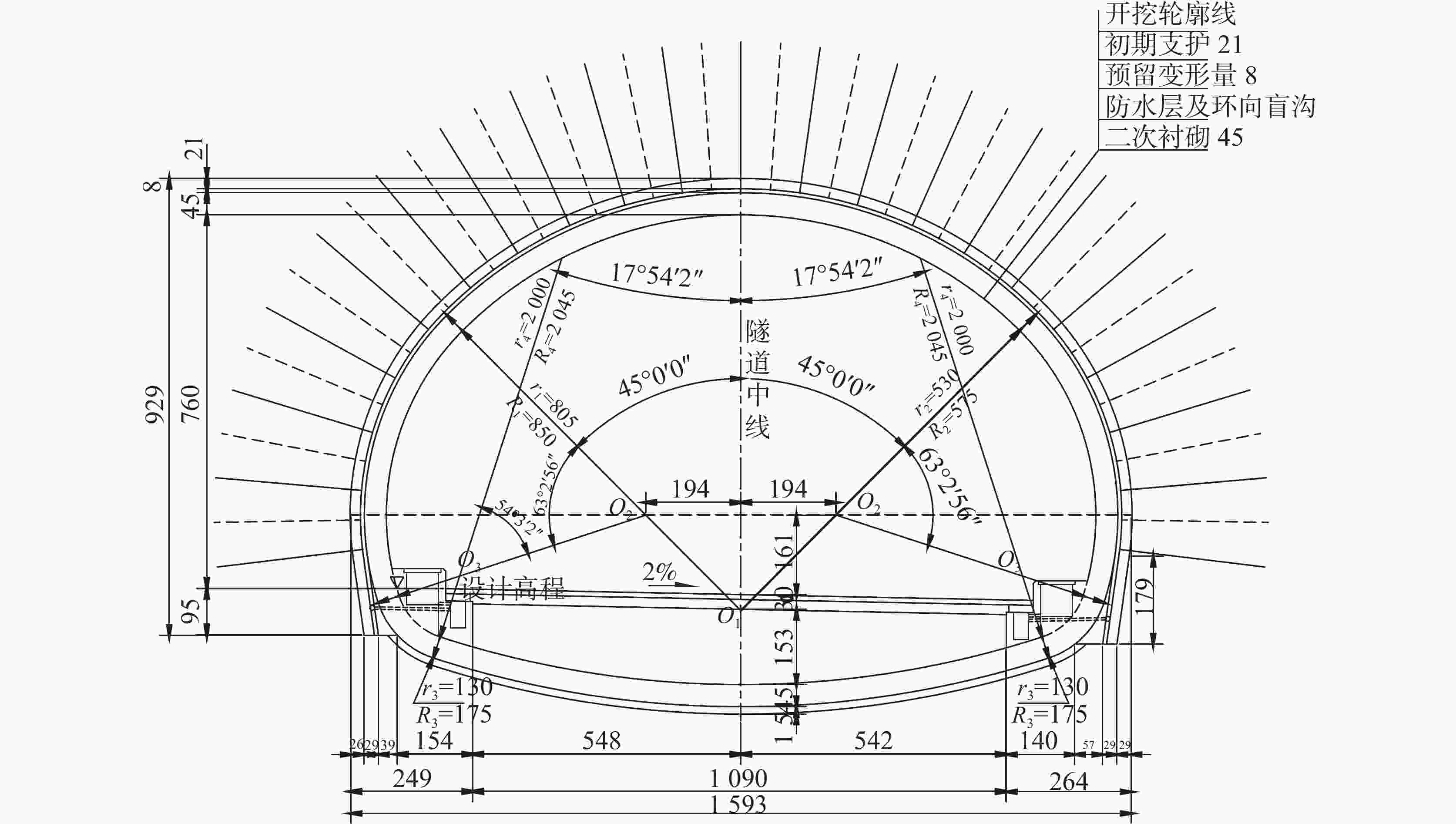
图 4 Ⅳ级围岩深埋段衬砌(单位mm)
Figure 4. Lining of Class IV surrounding rock at the deep-buried section
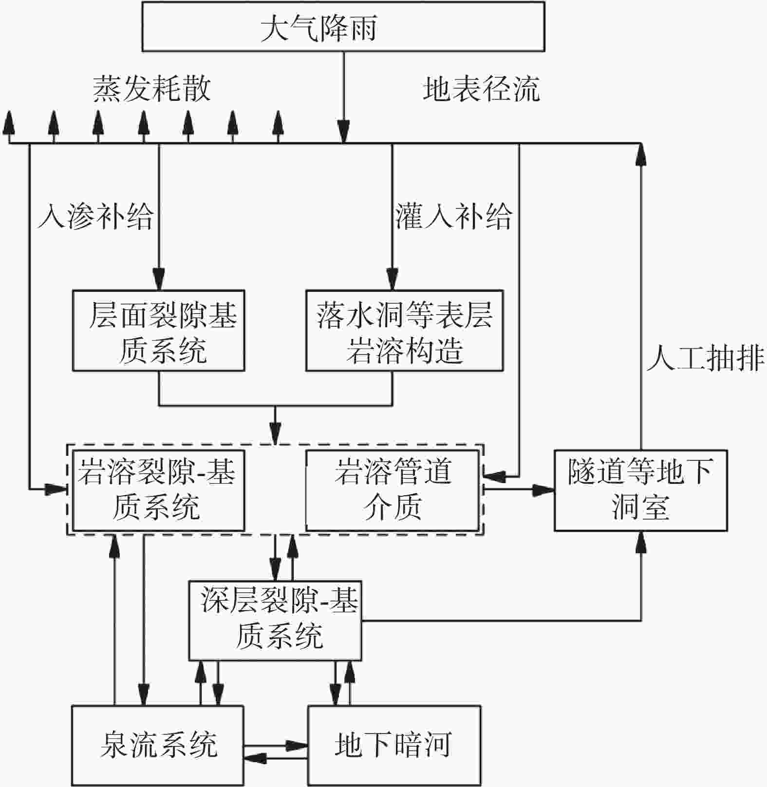
图 5 岩溶地下水渗入、储存、运移、排泄过程
Figure 5. Process of karst groundwater infiltration, storage, migration and discharge
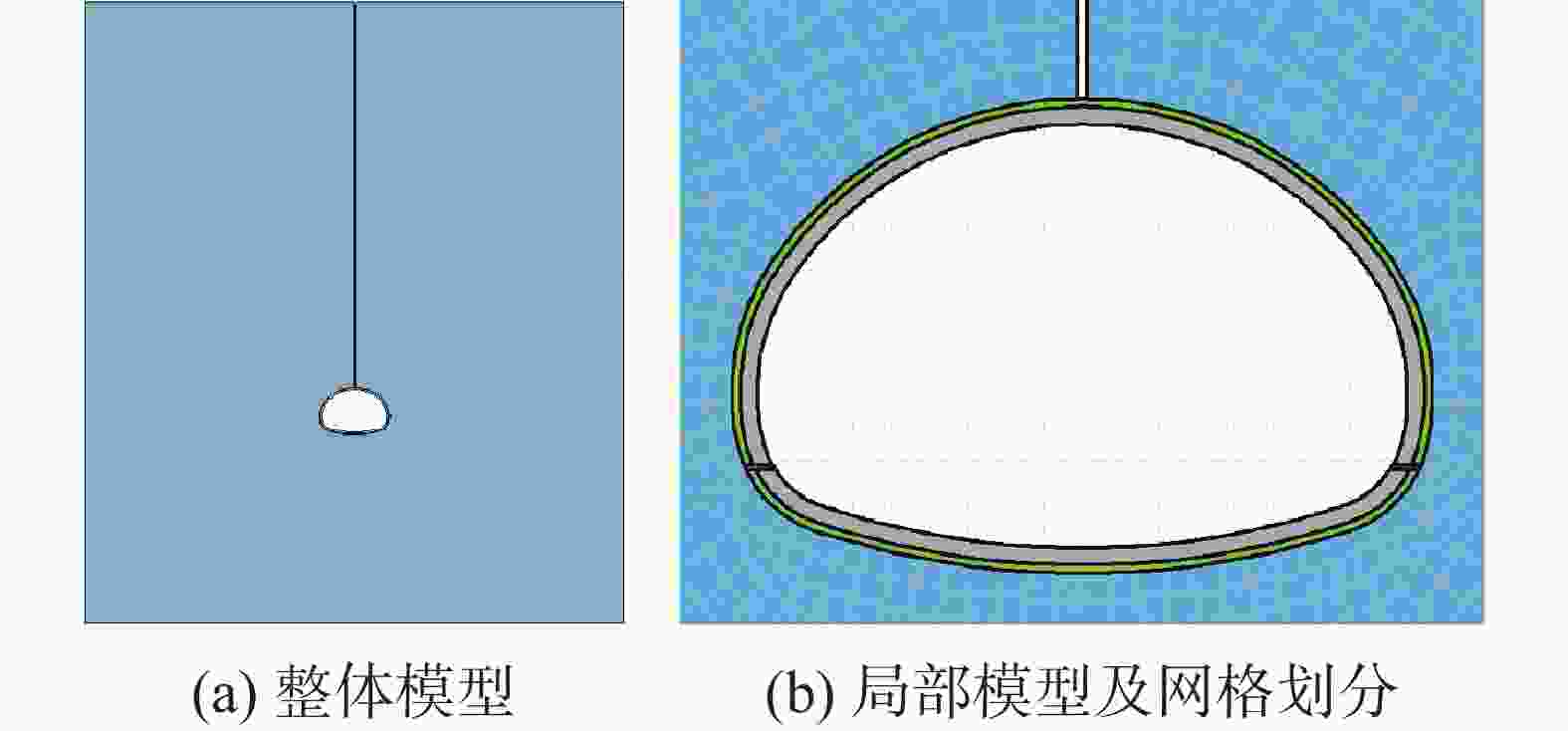
图 7 溶槽与衬砌边墙接触时的计算模型
Figure 7. Calculation model of water-eroded groove in contact with lining side wall
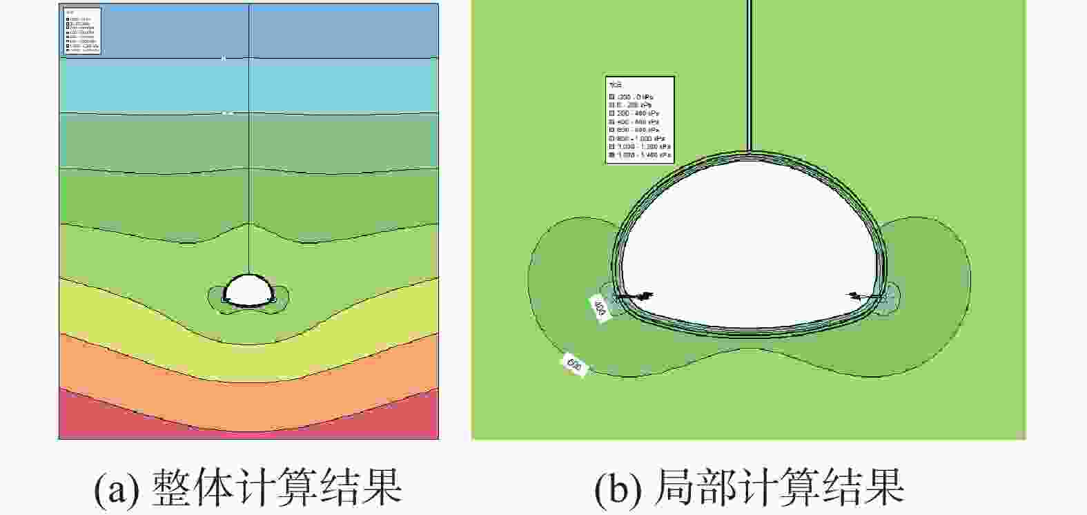
图 9 距离地表20 m水位条件下的渗流计算结果
Figure 9. Seepage calculation results at the 20-meter water level from the surface
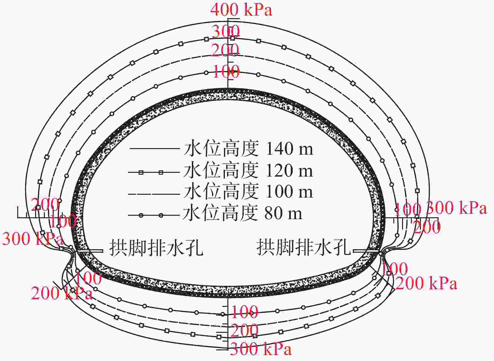
图 10 蓄水溶槽在不同水位条件下的隧道水压分布图
Figure 10. Tunnel water pressure distribution of water-eroded groove of water storage at different water levels
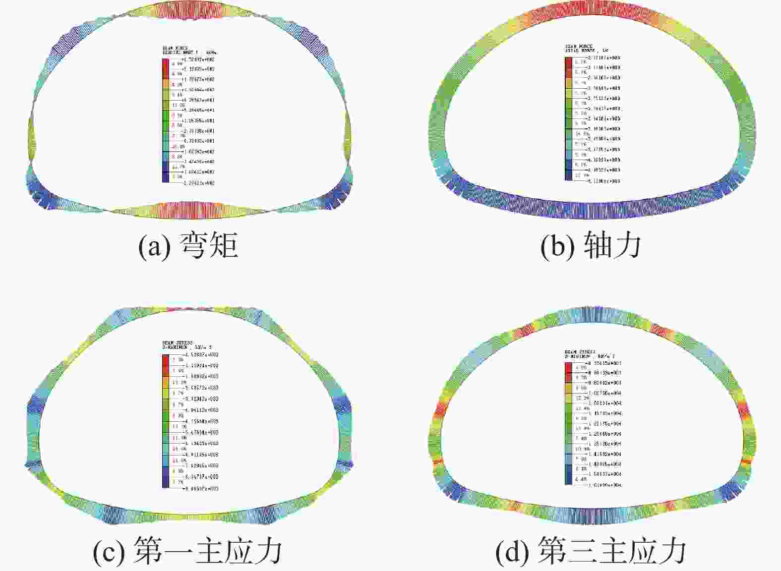
图 11 距离地表20 m水位条件下的隧道受力情况
Figure 11. Internal force of tunnel lining at the 20-meter water level from the surface
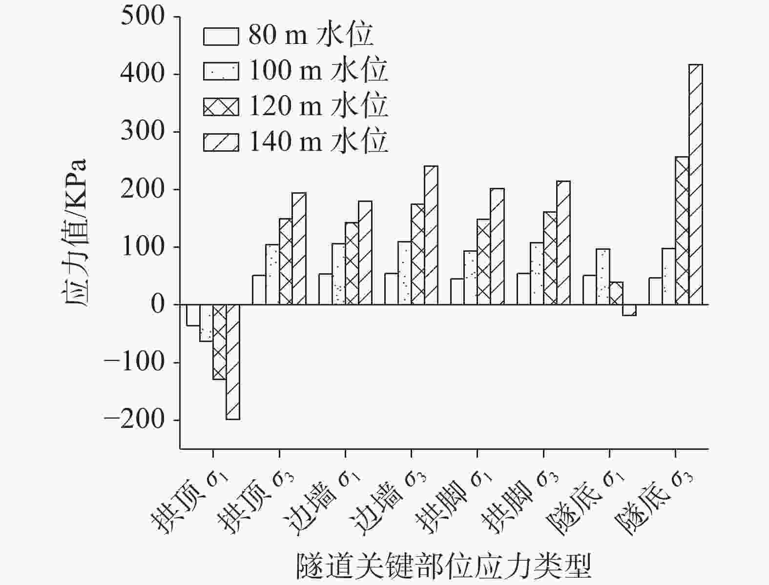
图 15 隧道关键部位主应力变化幅度
Figure 15. Variation amplitude of principal stress at the key points of tunnel
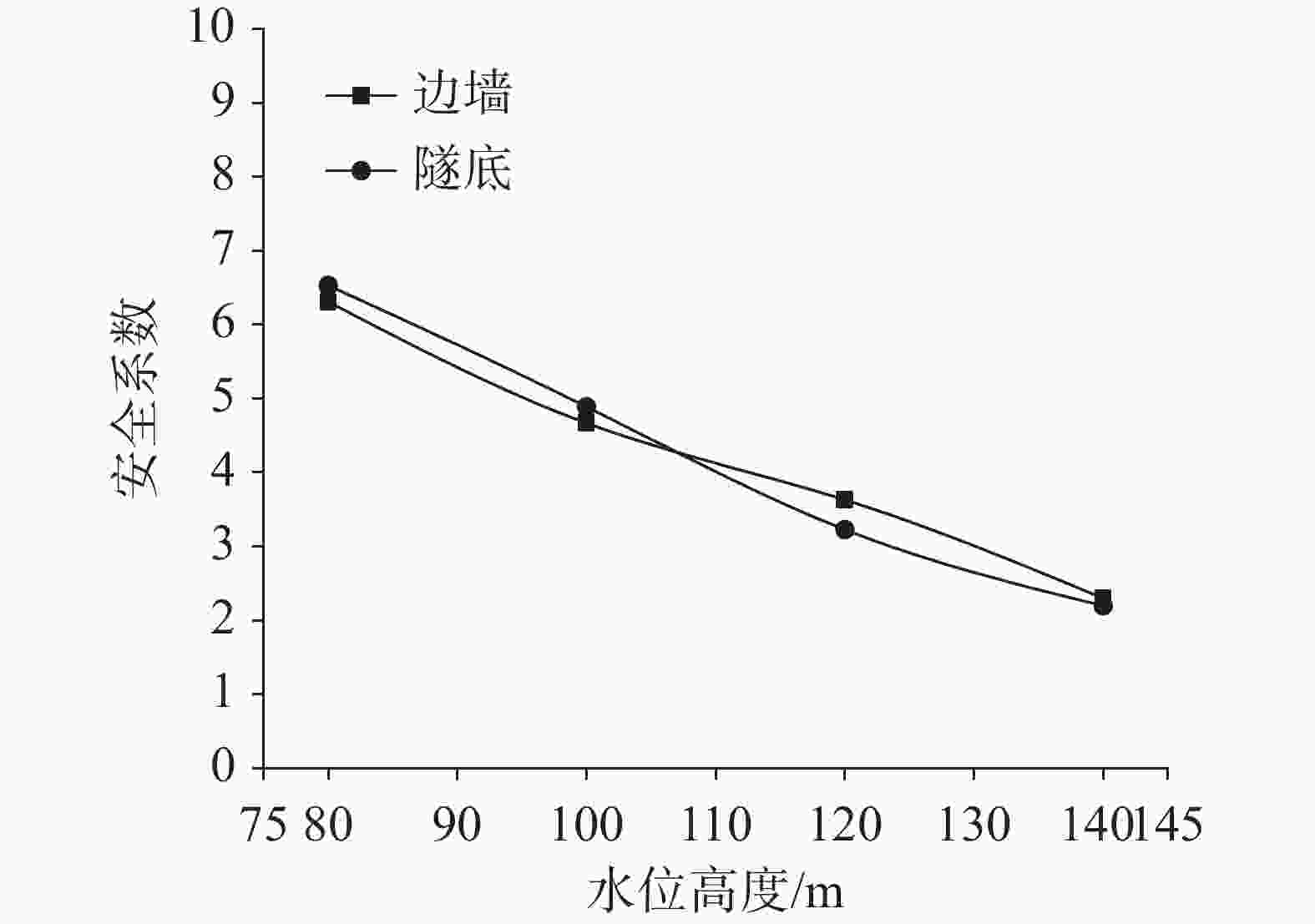
图 17 隧道边墙、隧底安全系数变化
Figure 17. Change of safety factor of tunnel side wall and tunnel inverted arc
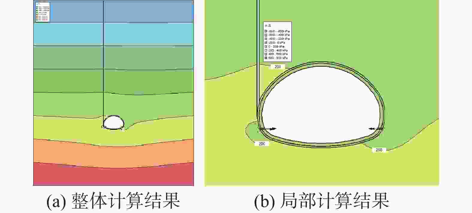
图 18 80 m水位条件下的渗流计算结果
Figure 18. Seepage calculation results at the 80-meter water level from the surface
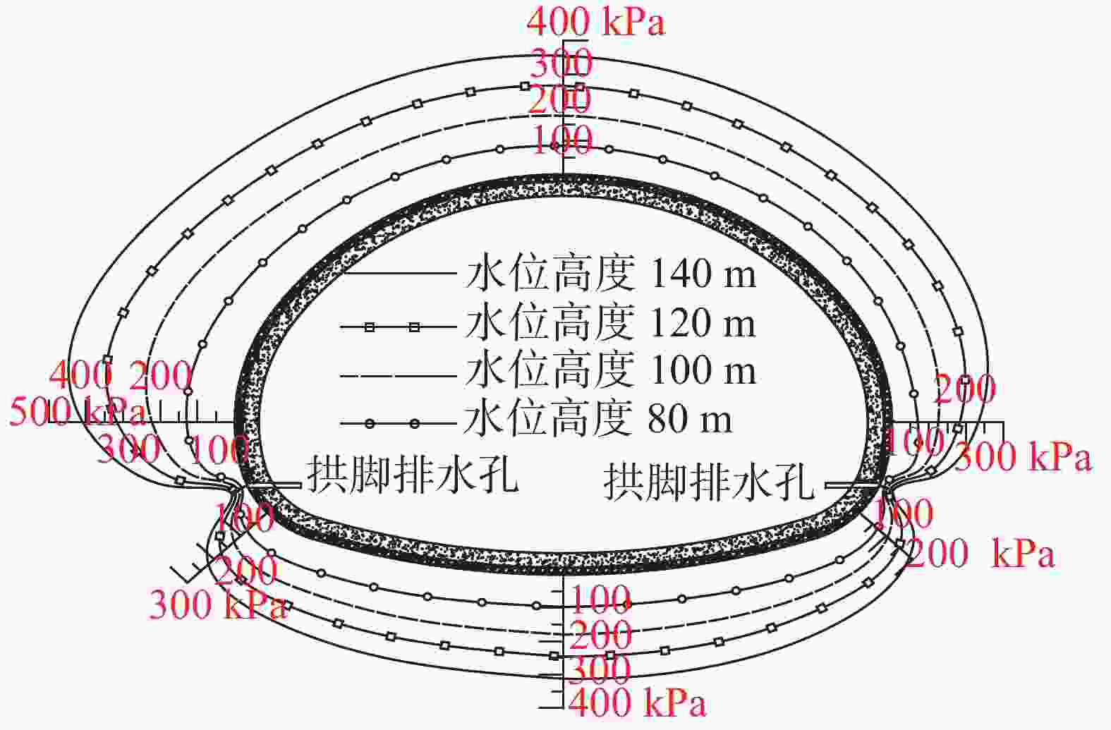
图 19 蓄水溶槽在不同水位条件下的隧道水压分布图
Figure 19. Tunnel water pressure distribution of water storage water-eroded groove under different water levels
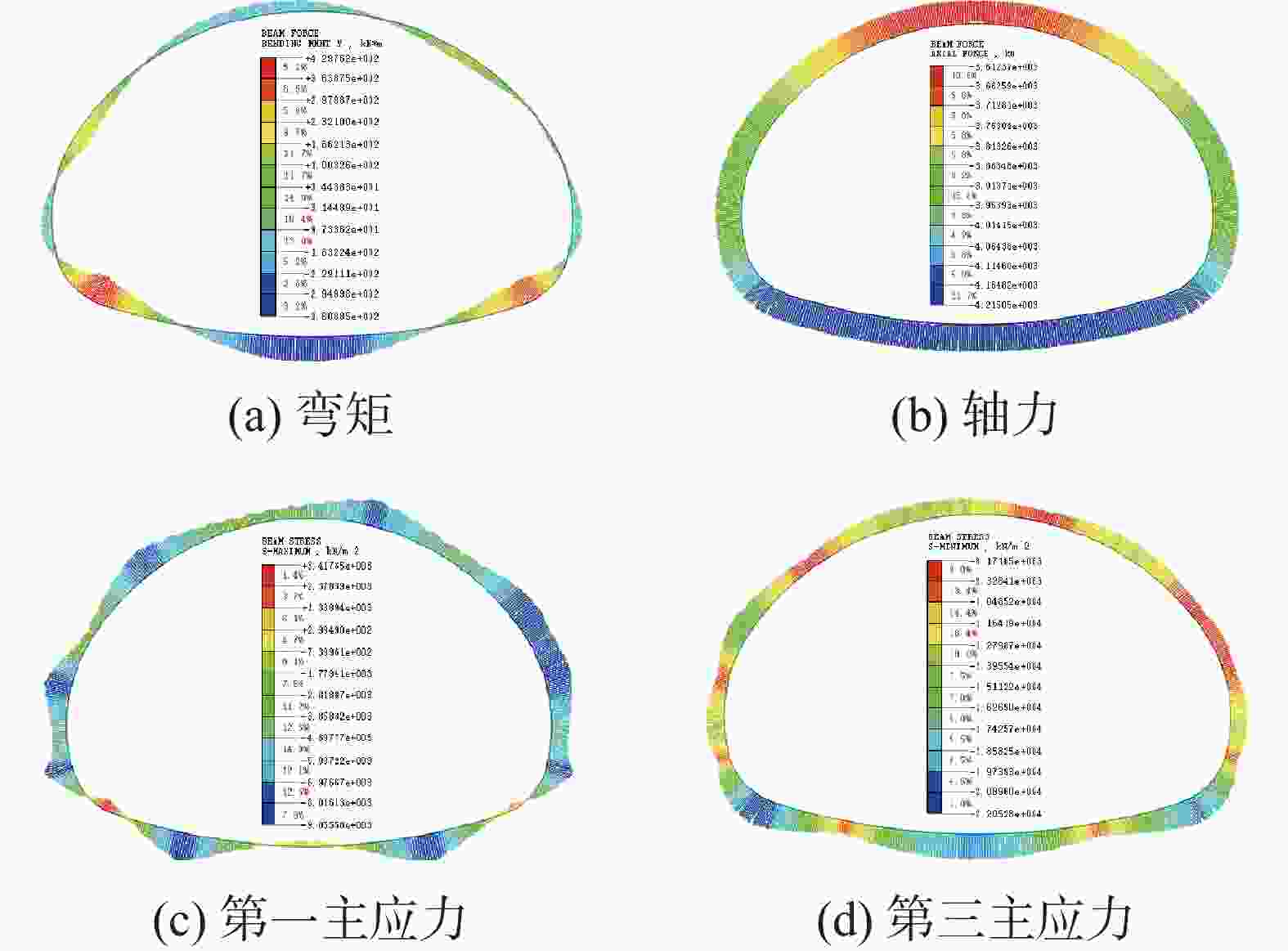
图 20 距离地表20 m水位条件下的隧道受力情况
Figure 20. Internal force of tunnel lining at the 20-meter water level from the surface
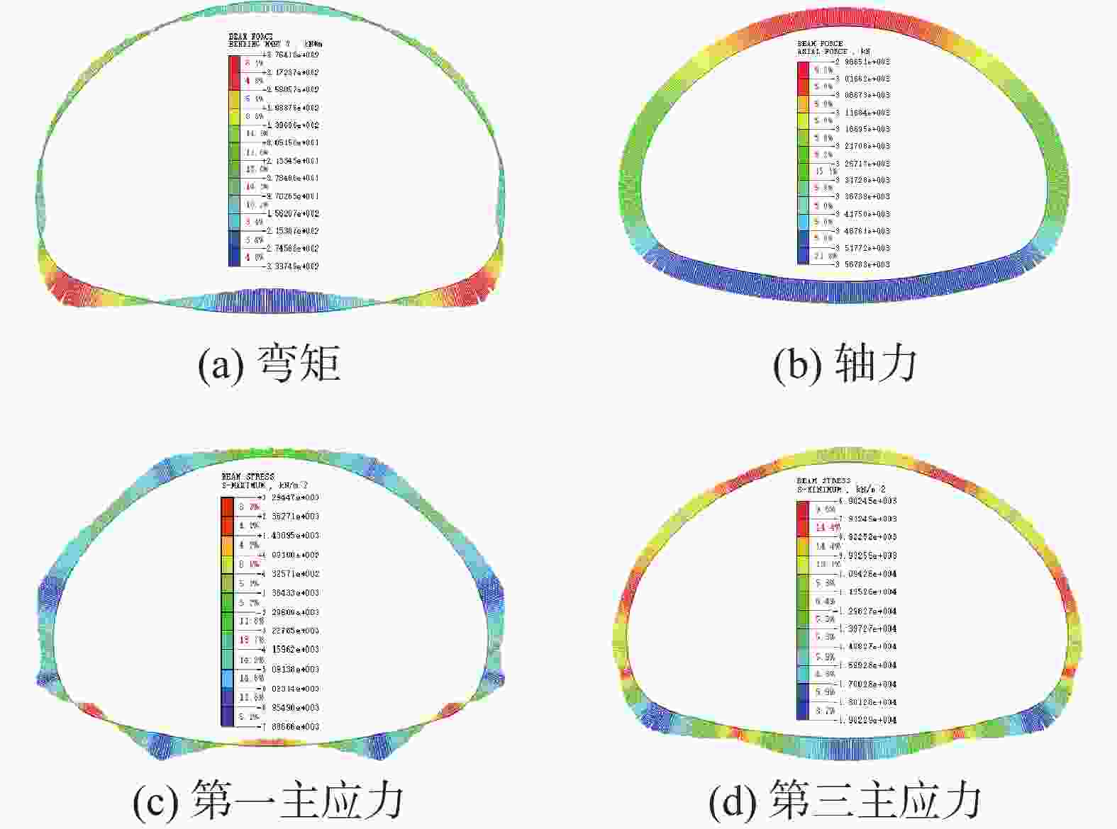
图 21 无溶槽时距离地表20 m水位条件下的隧道受力情况
Figure 21. Internal force of tunnel lining at the 20-meter water level from the surface without water-eroded groove
表 1 隧道Ⅳ级围岩支护参数
Table 1. Support parameters of Class IV surrounding rock of tunnel
初期支护 二次衬砌 C25喷砼 φ8钢筋网 φ22砂浆锚杆 C35钢筋砼 全环21 cm 全环@25×25 cm 拱墙@120×100 cm,L-3.5 m 45 cm  下载: 导出CSV
表 2 季节性降雨导致水位升降时的计算工况
Table 2. Calculation work conditions for the rise and fall of water level due to seasonal rainfall
工况 溶槽位置 水位/m 工况 溶槽位置 水位/m 1-0 拱顶 / 2-0 边墙 / 1-1 拱顶 140 2-1 边墙 140 1-2 拱顶 120 2-2 边墙 120 1-3 拱顶 100 2-3 边墙 100 1-4 拱顶 80 2-4 边墙 80 (注:拱顶溶槽宽0.25 m,竖直高度100 m;边墙溶槽宽0.25 m,竖直高度108 m。)
(Note: width of vault water-eroded groove=0.25 m; vertical height=100 m; width of the water-eroded groove of side wall=0.25m; vertical height=108 m)
下载: 导出CSV
表 3 无溶槽时的计算工况
Table 3. Calculation work conditions without water-eroded groove
工况 溶槽位置 水位/m 3-1 / 140 3-2 / 120 3-3 / 100 3-4 / 80
下载: 导出CSV
表 4 数值模拟计算参数
Table 4. Calculation parameters of numerical simulation
材料名称 弹性模量/MPa 密度/kg·m−3 泊松比 内摩擦角/° 粘聚力/kPa 渗透系数/cm·s−1 弹性抗力系数/MPa·m−1 石灰岩 23 500 2 300 0.28 30 450 1.65$ \times $10−5 600 初期支护 25 000 2 500 0.2 − − 1.25$ \times $10−6 / 二次衬砌 30 000 2 500 0.2 − − 不透水 / 排水管道 25 000 2 500 0.25 − − 1$ \times $10−3 /
下载: 导出CSV
表 5 溶槽在隧道拱顶时不同水位条件下隧道受力情况1
Table 5. Stress of tunnel lining at different water levels when the water-eroded groove is at tunnel vault 1
项目 拱顶 边墙 水位/m 轴力/kN 弯矩/kN.m k $ {\sigma _1} $/kPa $ {\sigma _3} $/kPa 轴力/kN 弯矩/kN.m k $ {\sigma _1} $/kPa $ {\sigma _3} $/kPa 无水 −896.8 102.9 8.7 1 055.9 −5 041.7 −1 232.3 20.0 9.8 −2 146.9 −3 330.0 80.0 −1 567.1 140.3 5.5 675.1 −7 640.2 −1 902.9 31.2 6.3 −3 303.9 −5 153.3 100.0 −2 230.7 180.6 4.0 394.7 −10 309.1 −2 567.2 42.9 4.7 −4 432.6 −6 977.2 120.0 −2 899.3 207.1 3.2 −306.5 −12 579.2 −3 233.9 66.5 3.6 −5 214.8 −9 158.1 140.0 −3 572.0 232.8 2.7 −1 039.2 −14 836.2 −3 904.6 90.2 2.3 −6 005.6 −11 348.1
下载: 导出CSV
表 6 溶槽在隧道拱顶时不同水位条件下隧道受力情况2
Table 6. Stress of tunnel lining at different water levels when the water-eroded groove is at tunnel vault 2
项目 拱脚 隧底 水位/m 轴力/kN 弯矩/kN·m k $ {\sigma _1} $/kPa $ {\sigma _3} $/kPa 轴力/kN 弯矩/kN·m k $ {\sigma _1} $/kPa $ {\sigma _3} $/kPa 无水 −1 294.6 −53.5 8.3 −1 292.1 −4 461.7 −1 358.7 1.5 9.7 −2 975.5 −3 063.0 80.0 −1 976.3 −84.7 5.3 −1 883.5 −6 899.9 −2 021.9 0.1 6.5 −4 492.5 −4 493.8 100.0 −2 651.8 −114.5 3.9 −2 501.4 −9 284.4 −2 682.5 −3.3 4.9 −5 863.1 −6 059.0 120.0 −3 343.2 −142.3 3.1 −3 213.1 −11 645.3 −3 394.0 114.1 3.2 −4 160.3 −10 924.3 140.0 −4 038.8 −171.3 2.6 −3 901.0 −14 049.4 −4 109.8 226.3 2.2 −2 428.0 −15 837.9
下载: 导出CSV
表 7 溶槽在隧道边墙时不同水位条件下隧道受力情况1
Table 7. Stress of tunnel lining at different water levels when the water-eroded groove is at tunnel side wall 1
项目 拱顶 隧底 左边墙 水位/m k $ {\sigma _1} $ $ {\sigma _3} $ k $ {\sigma _1} $ $ {\sigma _3} $ k $ {\sigma _1} $ $ {\sigma _3} $ 80 5.9 −172.9 −6 780 6.5 −4 473 −4 489 6.2 −3 110 −5 298 100 4.4 −1 316 −8 607 4.3 −4 181 −7 847 4.3 −3 978 −7 375 120 3.6 −2 914 −10 078 2.8 −1 657 −13 690 3.4 −4 612 −9 774 140 3 −4 612 −11 445 2.1 974.4 −19 701 2.7 −4 932 −12 520
下载: 导出CSV
表 8 溶槽在隧道边墙时不同水位条件下隧道受力情况2
Table 8. Stress of tunnel lining at different water levels when the water-eroded groove is at tunnel side wall 2
项目 右边墙 左拱脚 右拱脚 水位/m k $ {\sigma _1} $ $ {\sigma _3} $ k $ {\sigma _1} $ $ {\sigma _3} $ k $ {\sigma _1} $ $ {\sigma _3} $ 80 6.5 −3 558 −4 915 5.3 −1 832 −6 918 5.4 −2 217 −6 600 100 4.6 −4 402 −7 034 3.7 −2 443 −9 344 3.9 −2 577 −9 285 120 3.5 −4 814 −9 670 2.9 −2 836 −12 137 3 −2 428 −12 616 140 2.8 −5 040 −12 480 2.3 −2 749 −15 455 2.3 −1 213 −17 057
下载: 导出CSV
表 9 无溶槽时不同水位条件下隧道受力情况
Table 9. Stress of tunnel lining at different water levels without water-eroded groove
项目 拱顶 隧底 边墙 拱脚 水位/m k $ {\sigma _1} $ $ {\sigma _3} $ k $ {\sigma _1} $ $ {\sigma _3} $ k $ {\sigma _1} $ $ {\sigma _3} $ k $ {\sigma _1} $ $ {\sigma _3} $ 80 6.5 490.5 −6 428 7.4 −3 957 −4 003 7.2 −2 907 −4 514 6 −1 654 −6 077 100 4.8 92.5 −8 416 5.4 −4 661 −5 681 5.4 −3 823 −5 983 4.6 −2 112 −8 044 120 4.1 −1 383 −9 398 3.2 −1 130 −11 991 4.2 −4 126 −8 109 3.6 −2 689 −10 048 140 3.5 −2 623 −10 561 2.4 1 763.6 −17 617 3.4 −4 414 −10 201 2.9 −2 557 −12 747
下载: 导出CSV
-
[1] 左太安, 张凤太, 于世杰, 黎娇, 樊昊, 叶丹. 中国岩溶地区石漠化贫困问题研究进展[J]. 中国岩溶, 2022, 41(6): 915-927.ZUO Taian, ZHANG Fengtai, YU Shijie, LI Jiao, FAN Hao, YE Dan. A study on poverty caused by rocky desertification in karst areas of China[J]. Carsologica Sinica, 2022, 41(6): 915-927. [2] 李阳兵, 侯建筠, 谢德体. 中国西南岩溶生态研究进展[J]. 地理科学, 2002(3):365-370. doi: 10.3969/j.issn.1000-0690.2002.03.019LI Yangbing, HOU Jianjun, XIE Deti. The recent development of research on karst ecology in Southwest China[J]. Scientia Geographica Sinica, 2002(3):365-370. doi: 10.3969/j.issn.1000-0690.2002.03.019 [3] 王刚, 王立川, 仇文革, 龚伦, 吴剑. 关于季节性岩溶管道流对某快速铁路隧道衬砌破坏的分析与思考[J]. 现代隧道技术, 2016, 53(6):210-218.WANG Gang, WANG Lichuan, QIU Wenge, GONG Lun, WU Jian. Analysis and considerations of an express railway tunnel lining failure by seasonal karst conduct flow[J]. Modern Tunnelling Technology, 2016, 53(6):210-218. [4] 郑波, 吴剑, 郭瑞. 季节性岩溶隧道结构安全预警体系构建及对策[J]. 现代隧道技术, 2019, 56(Suppl.2):67-72. doi: 10.13807/j.cnki.mtt.2019.S2.010ZHENG Bo, WU Jian, GUO Rui. Building-up of a safety early-warning system for seasonal karst tunnel structure and its prevention countermeasures[J]. Modern Tunnelling Technology, 2019, 56(Suppl.2):67-72. doi: 10.13807/j.cnki.mtt.2019.S2.010 [5] 陈仲达, 林志, 陈相, 杨红运, 陆原恩, 赵益鑫. 基于非线性渗流模型的管道型岩溶隧道突水机理研究[J]. 现代隧道技术, 2022, 59(1):149-155. doi: 10.13807/j.cnki.mtt.2022.01.017CHEN Zhongda, LIN Zhi, CHEN Xiang, YANG Hongyun, LU Yuanen, ZHAO Yixin. Study on the water inrush mechanism in tunnelling with karst conduits based on nonlinear seepage model[J]. Modern Tunnelling Technology, 2022, 59(1):149-155. doi: 10.13807/j.cnki.mtt.2022.01.017 [6] 杨坤, 肖维民, 王丽君, 王建, 陈凤辉. 上伏落水洞岩溶隧道围岩力学响应数值分析[J]. 地下空间与工程学报, 2021, 17(Suppl.2):637-644.YANG Kun, XIAO Weimin, WANG Lijun, WANG Jian, CHEN Fenghui. Numerical analysis of the mechanical response of karst tunnel surrounding rock considering the influence of sinkhole[J]. Chinese Journal of Underground Space and Engineering, 2021, 17(Suppl.2):637-644. [7] 金美海, 刘新荣, 钟祖良. 岩溶隧道拱顶局部水压作用下衬砌受力特征研究[J]. 地下空间与工程学报, 2021, 17(4): 1099-1105, 1131.JIN Meihai, LIU Xinrong, ZHONG Zuliang. Study on the mechanical characteristics of the lining structure of the karst tunnel under the action of local high water pressure on the vault[J]. Chinese Journal of Underground Space and Engineering, 2021, 17(4): 1099-1105, 1131. [8] 马栋. 深埋岩溶对隧道安全影响分析及处治技术研究[D]. 北京: 北京交通大学, 2012.MA Dong. Study on impact mechanism of deep buried karst to tunnel safety and the treatment technique[D]. Beijing: Beijing Jiaotong University, 2012. [9] 庄旭峰, 孙东. 实例分析隧道建设对岩溶水的影响[J]. 中国岩溶, 2016, 35(6):681-687.ZHUANG Xufeng, SUN Dong. Influence of tunnel construction on karst water: Case analyse[J]. Carsologica Sinica, 2016, 35(6):681-687. [10] 许振浩, 李术才, 李利平, 陈军, 张之淦, 石少帅. 一种典型的岩溶隧道衬砌压裂突水灾害成因与防治[J]. 岩石力学与工程学报, 2011, 30(7):1396-1404.XU Zhenhao, LI Shucai, LI Liping, CHEN Jun, ZHANG Zhigan, SHI Shaoshuai. Cause, disaster prevention and controlling of a typical kind of water inrush and lining fracturing in karst tunnels[J]. Chinese Journal of Rock Mechanics and Engineering, 2011, 30(7):1396-1404. [11] 聂志凌. 水压充填型岩溶隧道突水机理及衬砌结构力学特性研究[D]. 成都: 西南交通大学, 2009.NIE Zhiling. Analysis for water burst mechanism and study on mechanical features of tunnel lining in water filled karst area[D]. Chengdu: Southwest Jiaotong University, 2009. [12] 李贻伟. 岩溶公路隧道围岩—支护结构受力特性数值模拟分析[D]. 重庆: 重庆交通大学, 2010.LI Yiwei. Numerical simulation analysis of mechanical characteristics of surrounding rock & support structure of road tunnel in karst region[D]. Chongqing: Chongqing Jiaotong University, 2010. [13] 朱海涛. 齐岳山隧道衬砌水压力特征与岩溶处治技术研究[D]. 北京: 北京交通大学, 2011.ZHU Haitao. Study on the rule of water pressure upon lining and treatment technique upon Qiyueshan karst[D]. Beijing: Beijing Jiaotong University, 2011. [14] 王一鸣. 高水压岩溶隧道衬砌结构受力特征和防排水设计研究[D]. 长沙: 中南大学, 2014.WANG Yiming. Research on mechanical characters and drainage of karst tunnel with high water pressure[D]. Changsha: Central South University, 2014. [15] 屈若枫. 武汉地铁穿越区岩溶地面塌陷过程及其对隧道影响特征研究[D]. 武汉: 中国地质大学, 2017.QU Ruofeng. Research on the evolutive process of karst collapse and the impact mechanism of the karst on subway tunnel in Wuhan subway crossing area[D]. Wuhan: China University of Geosciences, 2017. [16] 谭信荣, 樊浩博, 宋玉香, 刘勇, 杨海宏. 管道型岩溶隧道衬砌结构受力特征试验研究[J]. 地下空间与工程学报, 2021, 17(6):1847-1856.TAN Xinrong, FAN Haobo, SONG Yuxiang, LIU Yong, YANG Haihong. Experimental study on the mechanical characteristics of the lining structure of pipe-type karst tunnel[J]. Chinese Journal of Underground Space and Engineering, 2021, 17(6):1847-1856. [17] 任一凡. 岩溶洼地隧道衬砌结构安全性数值模拟研究[D]. 太原: 太原科技大学, 2021.REN Yifan. Numerical simulation study on safety of tunnel lining structure in karst depression[D]. Taiyuan: Taiyuan University of Science and Technology, 2021. [18] 余洪璋. 瞬时强降雨下铁路岩溶隧道衬砌强度探讨:以贵州织毕铁路元宝山隧道为例[J]. 中国岩溶, 2019, 38(6):916-923.YU Hongzhang. Discussion on lining strength of railway tunnels in karst areas under instantaneous heavy rainfall: An example of the Yuanbaoshan tunnel of Zhijin-Bijie railway in Guizhou Province[J]. Carsologica Sinica, 2019, 38(6):916-923. [19] 邹育麟, 何川, 何聪, 张政, 汪波. 重庆岩溶地区季节性富水营运隧道渗漏水病害特征及其成因机制分析[J]. 现代隧道技术, 2014, 51(4):18-27.ZOU Yulin, HE Chuan, HE Cong, ZHANG Zheng, WANG Bo. Analysis of water seepage characteristics and formation mechanisms in seasonal water-rich tunnels in a karst area of Chongqing[J]. Modern Tunnelling Technology, 2014, 51(4):18-27. [20] 中华人民共和国交通运输部. JTG3370.1-2018公路隧道设计规范[S]. 北京: 人民交通出版社, 2018 [21] 中华人民共和国交通运输部. JTG/T D70-2010公路隧道设计细则[S]. 武汉: 人民交通出版社, 2010. -


 点击查看大图
计量
- 文章访问数: 272
- HTML浏览量: 77
- PDF下载量: 45
- 被引次数: 0
